top of page
EFFECTIVE THICKNESS - Ceramic Shell Structures
Harvard Graduate School of Design
In collaboration with Zach Seibold, Ling-Li Tseng & Yingyi Wang
This research investigates the assembly of funicular shell structures using a single layer of flat ceramic tiles. The objective is to synthesize recent advances in structural prediction software with existing means and methods of on-site assembly. The primary area of investigation is at the scale of the tectonic unit - most specifically introduction of complexity at the scale of the unit can simplify assembly of forms that are difficult to realize in the context of modern construction. The project simulates an industrial production scenario in which components for a given shell structure can be fabricated using a wire cutter-equipped 6-axis robotic arm. It aims to increase the adaptability and applicability of ceramic shell structures.

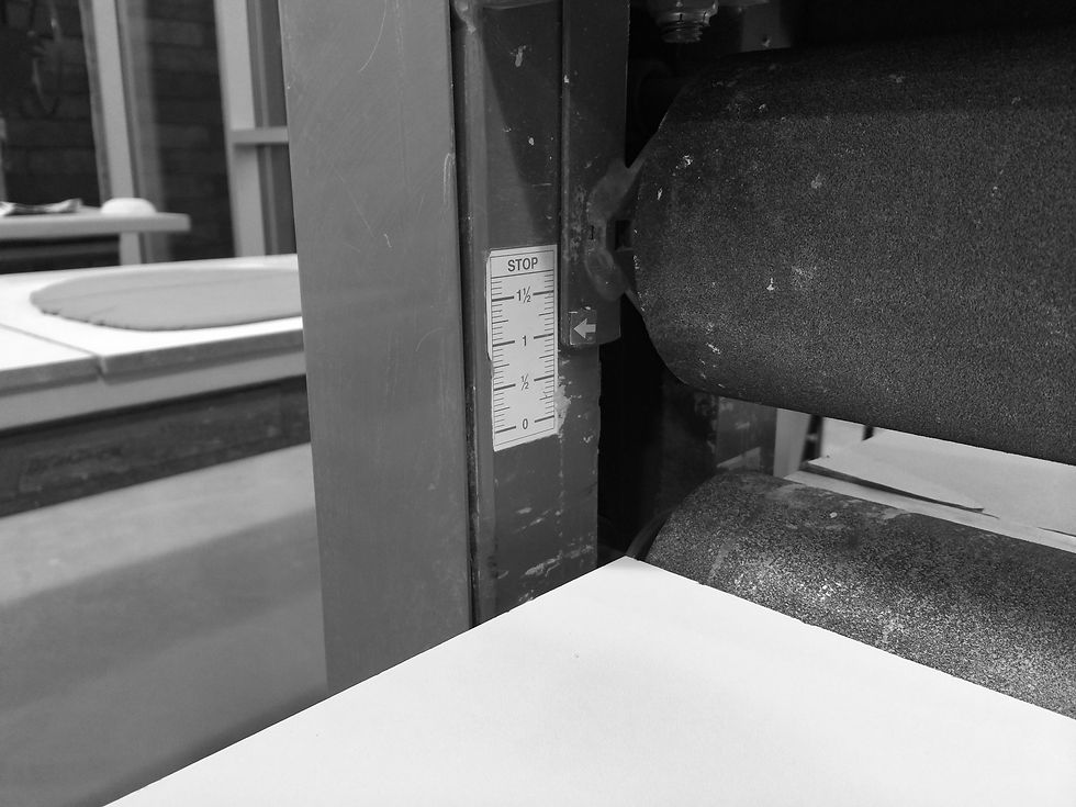
In an effort to gain an understanding of the potential for clay tile shrinkage and deformation, the design team also developed a process for producing several prototype tiles out of earthenware clay. The design team produced a number of 1.5 inch thick clay slabs as an approximation of industrially extruded slabs. In order to accurately mimic the shape of the tiles used in the concrete shell prototype, the geometry of the top and bottom face of each module was laser cut from acrylic sheets. These pairs of laser cut sheets we used as guides to simulate a robotic wirecutting process. Registration holes in each acrylic plate were used to control the relative position of each pair of plates. Four adjacent tiles identical in shape and size to the concrete pavers were produced. While leather-hard, these tiles were able to fit together with a high degree of precision.
EXHIBITION AT THE HARVARD CERAMIC LAB


The project proposes to strengthen the relationship between contemporary digital form-finding techniques and the process of assembly by infusing an existing method of production with computational design techniques and computer-aided manufacturing. The tectonic system provides a simplified assembly method and increased structural performance through the design of the joints between tectonic units. The implementation of variable ruled surfaces at the seams between units provides increased shear resistance much in the same way that multiple layers of tiles do in Catalan, etc. vaulting systems.

b4.jpg

b3.jpg

b5.jpg

b2.jpg

b6.jpg

b1.jpg


Upon firing, the design team recorded shrinkage of 4-5% of the tiles total size. The tiles shrunk uniformly enough to still interlock with a reasonable degree of precision relative to their overall size.

The design team developed two major prototypes to test different aspects of the proposed construction system. A full-scale prototype shell was developed to test the potential of the assembly system. For the construction of the prototype, the design team chose to simulate the proposed ceramic production process using industrially produced concrete pavers and a water jet-equipped robotic arm. The use of concrete pavers allowed the design team to avoid many of the challenges encountered in early clay tile studies – including irregularities in the slab production and firing process and the differential shrinkage of tiles. The waterjet was chosen to approximate an industrial wirecutter because of their similar geometric capabilities – most notably the ability to produce ruled surfaces through the entire depth of a given material.


The initial surface geometry for the prototype shell was generated using Rhinoceros 5 and the Thrust Network Analysis tools available in the RhinoVAULT plugin . From the initial funicular geometry, the design team generated a triangular grid with a spacing related size of the stock concrete tiles used in the shell construction. The initial grid pattern was constructed on the XY plane and projected onto the funicular surface. Once the surface was divided into individual triangles based on this pattern, and extruded to the thickness of our raw material, the team mapped a specific oscillating curve to each point. This curve was scaled based on the specific edge lengths of each surface. The specific oscillations of each curve were confined to the maximum achievable by the waterjet cutter – roughly 45 degrees from vertical. To generate edge surfaces from the curves on the patch surface, we used the “fin” command. Finally, the “fin” surfaces were trimmed with the initial offset surface to get the final geometry of each module. Each module was then oriented on a model of the concrete tiles. Wireframe geometry that described the edges of each module was used to define toolpaths for the robot. Cutting paths were generated in Mastercam X7, then verified and checked for collisions in Robotmaster. The design team produced several studies to determine the optimal cutting speed for the waterjet on the given material.

While the waterjet-cut concrete paver prototype exists as a proof-of-concept for the tectonic geometry goals of the project, combining the existing process of clay extrusion with robotic wire cutting could adapt this process to be a nearly zero-waste method of producing double-curvature shells. The wire cutting system would allow for the low to medium-volume production of individually customized ceramic modules. Future work on this project can continue on a number of aspects, including; identifying the relationship between surface curvature and unit size, refining the swarf geometry generated at the contact faces, exploring the swarf geometry as it relates to the force diagram of a given shell structure and developing a more universal approach to a formwork system.


DESIGN AND FABRICATION PROCESS

bottom of page